
Question 96
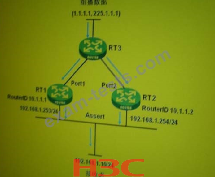
In the PIM-DM network as shown in the figure, part of the unicast routing table of routers RT1 and RT2 is as follows:
<RT1>display ip routing-table
Routing Tables: Public
Destination/MaskProtoPreCost NextHop Interface
1.1.0.0/16xxxxP1-1 C1-110.1.1.1POI11
1.1.1.0/24xxxxP1-2 C1-210.1.1.1Port1
<RT2>display ip routing-table
Routing Tables: Public
Destination/MaskProtoPreCost NextHop Interface
1.1.1.0/24XXXX P2-1 C2-111.1.1.1Port2
1.1.1.1/32XXXX P2-2 C2-211.1.1.1Port2
Then, when routers RT1 and RT2 perform Assert, the winner should be
Question 97
The following statements about the PIM SM joining process are correct.
Question 98
Two routers RTA and RTB are connected through a LAN to form a VRRP backup group. The configuration of each interface is as follows:
GigabitEthernet1/0.1 of RTA
vlan-type dot1 q vid 2
ip address 192.168.0.252 255.255.255.0
vrrp vrid 1 virtual-ip 192.168.0.254
vrrp vrid 1 priority 120
GigabitEthernet1/0.2 of RTA
vlan-type dot1 q vid 3
ip address 192.168.1.252 255.255.255.0
vrrp vrid 2 virtual-ip 192.168.1.254
vrrp vrid 2 priority 120
GigabitEthernet1/0.1 of RTB:
vlan-type dot1 q vid 2
ip address 192.168.0.253 255.255.255.0
vrrp vrid 1 virtual-ip 192.168.0.254
GigabitEthernet1/0.2 of RTB:
vlan-type dot1 q vid 3
ip address 192.168.1.253 255.255.255.0
vrrp vrid 2 virtual-ip 192.168.1.254
The IP addresses of HostA and HostB in the LAN are 192.168.0.1 and 192.168.1.1 respectively. From the above information, we can know
Question 99
Which statement is correct about the communication between switch VLANs?
Question 100
The switches SWA and SWB are connected together through two optical fiber Gigabit Ethernet links, and the switch SWA has the following interface configuration:
[SWA]interface GigabitEthernet 1/0/1
[SWA-GigabitEthernet1/0/1]gvrp
[SWA-GigabitEthernet1/0/1]port link-type trunk
[SWA-GigabitEthernet1/0/1]port trunk permit vlan 1 10
[SWA]interface GigabitEthernet 1/0/2
[SWA-GigabitEthernet1/0/2]port link-type trunk
[SWA-GigabitEthernet1/0/2]port trunk permit vlan 1 10
If you want to configure link aggregation to aggregate these two links together, if the configuration on the SWB is correct, you can know from the above information
Premium Bundle
Newest GB0-371-ENU Exam PDF Dumps shared by BraindumpsPass.com for Helping Passing GB0-371-ENU Exam! BraindumpsPass.com now offer the updated GB0-371-ENU exam dumps, the BraindumpsPass.com GB0-371-ENU exam questions have been updated and answers have been corrected get the latest BraindumpsPass.com GB0-371-ENU pdf dumps with Exam Engine here: