
Question 101
Regarding the comparison of unicast, multicast and broadcast, there are correct
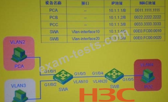
Question 102
In the switching network as shown in the figure, set VLAN10 as Isolate-userW, VLAN2 and VLAN3 as the Secondary VLAN of VLAN 10 on the switch SWA; create VLAN2? VLAN20 on the switch SWB, and set VLAN20 as Isolate-user-vlan, VLAN4 As the Secondary VLAN of VLAN20, after setting the IP address of each device as shown in the figure, check the MAC address table on the SWA, and you can determine that the PCC belongs to
Question 103
Two routers RTA and RTB are connected through a LAN to form a VRRP backup group. The interface configuration of each router is as follows:
GigabitEthernet1/0 of RTA
ip address 192.168.0.252 255.255.255.0
ip address 192.168.1.252 255.255.255.0 sub
vrrp vrid 1 virtual-ip 192.168.0.254
vrrp vrid 1 priority 120
vrrp vrid 2 virtual-ip 192.168.1.254
GigabitEthernet1/0 of RTB
ip address 192.168.0.253 255.255.255.0
ip address 192.168.1.253 255.255.255.0 sub
vrrp vrid 1 virtual-ip 192.168.0.254
vrrp vrid 2 virtual-ip 192.168.1.254
vrrp vrid 2 priority 120
From the above information-know
Question 104
In the PIM-DM network as shown in the figure, part of the unicast routing table of routers RT1 and RT2 is as follows
<RT1>display ip routing-table
Routing Tables: Public
Destination/MaskProtoPreCost NextHop Interface
10.1.1.0/30 Direct 0010.1.1.2Port1
10.1.1.1/32 Direct 0010.1.1.1Port1
10.1.1.2/32 Direct 00127.0.0.1 InLoopO
11.1.1.0/30 Direct 0011.1.1.1Port2
11.1.1.1/32 Direct 00127.0.0.1 InLoopO
12.1.1.0/30 Direct 0012.1.1.1Port3
12.1.1.1/32 Direct 00127.0.0.1 InLoopO
100.1.1.0/240SPF 10 1563 10.1.1.1 Portl
127.0.0.0/8 Direct 00127.0.0.1 InLoopO
127.0.0.1/32Direct 00127.0.0.1 InLoopO
100.1.0.0/160SPF 10 311.1.1.2 Port2
<RT2>display ip routing-table
Routing Tables: Public
Destination/MaskProtoPreCost NextHop Interface
20.1.1.0/30 Direct 0020.1.1.2Port1
20.1.1.1/32 Direct 0020.1.1.1 Portl
20.1.1.2/32 Direct 00127.0.0.1 InLoopO
11.1.1.0/30 Direct 0011.1.1.2Port2
11.1.1.2/32 Direct 00127.0.0.1 InLoopO
22.1.1.0/30 Direct 0022.1.1.1Port3
22.1.1.1/32 Direct 00127.0.0.1 InLoopO
100.1.1.0/240SPF 10 1564 11.1.1.1 Port2
127.0.0.0/8 Direct 00127.0.0.1 InLoopO
127.0.0.1/32Direct 00127.0.0.1 InLoopO
100.1.0.0/160SPF 10 220.1.1.1 Portl
Then, the (S, G) entry and exit interface lists of routers RT1 and RT2 are respectively
Question 105
In the network shown in the figure, the switch SWA is a two-layer switch, and the router RTA is the gateway of each PC. The following configuration is made on the router RTA:
[RTA]interface Ethernet 0/0.1
[RTA-Ethernet0/0.1]ip address 10.10.10.1 255.255.255.0
[RTA-EthernetO/0.1 ]vlan-type dotlq vid 1
[RTA-Ethernet0/0.1 Jinterface ethernet 0/0.2
[RTA-Ethernet0/0.2]ip address 20.20.20.1 255.255.255.0
[RTA-Ethernet0/0.2]vlan-type dotlq vid 2
[RTA-Ethernet0/0.2]interface ethernet 0/0.3
[RTA-Ethernet0/0.3]ip address 30.30.30.1 255.255.255.0
[RTA-Ethernet0/0.3]vlan-type dotlq vid 3
After completing the phase configuration on the switch SWA, PCA, PCB and PCC can all ping their own gateway. The following is correct about the switch SWA port Ethernet1/0/4 (choose one or more)