Question 11
The IP address of the host PCA is 40.1.1.1, the MAC address is 0011.1111.1111, and it is connected to the GigabitEthernet1/0/1 port of the switch SWA. The following commands are configured on the switch SWA:
[SWA]vlan 10
[SWA-vlan10]quit
[SWA]vlan 20
[SWA-vlan20]protocol-vlan ipv4
[SWA-vlan20]quit
[SWA]vlan 30
[SWA-vlan30]quit
[SWA]mac-vlan mac-address 0011-1111-1111 vlan 30
[SWA]vlan 40
[SWA-vlan40]ip-subnet-vlan ip 50.1.1.0 255.255.255.0
[SWA-vlan40]quit
[SWA]interface GigabitEthernet 1/0/1
[SWA-GigabitEthernet1/0/1]port link-type hybrid
[SWA-GigabitEthernet1/0/1]port hybrid pvid vlan 10
[SWA-GigabitEthernet1/0/1]port hybrid vlan 10 20 30 40 untagged
[SWA-GigabitEthernet1/0/1]port hybrid protocol-vlan vlan 20 0
[SWA-GigabitEthernet1/0/1]port hybrid ip-subnet-vlan vlan 40
[SWA-GigabitEthernet1/0/1]mac-vlan enable
[SWA-GigabitEthernet1/0/1]vlan precedence ip-subnet-vlan
After the configuration is complete, it can be judged that PCA will join
Question 12
The customer's two switches SWA and SWB are connected together through seven Ethernet cables, and are configured with dynamic link aggregation. The corresponding ports on the switch SWA are Ethernet 1/0, Ethernet 1/0/2, and Ethernet 1/0/3 , Ethernet 1/0/4, Ethernet 1/0/5, Ethernet 1/0/6, Ethernet1/0/7 If the switches SWA and SWB only support 6 ports per aggregation group, and the SWA switch has the following configuration:
[SWA]interface Ethernet 1/0/7
[SWA-Ethernet1/0/7]lacp port-priority 4096
The LACP status output on the device is as follows:
[SWA]display lacp system-id
Actor System ID: 0x8000, 00e1-fc00-5000
[SWB]display lacp system-id
Actor System ID: 0x8000, 00e0-fc43-7384
From the above information, we can know_
Question 13
Which statement is correct about the communication between switch VLANs?
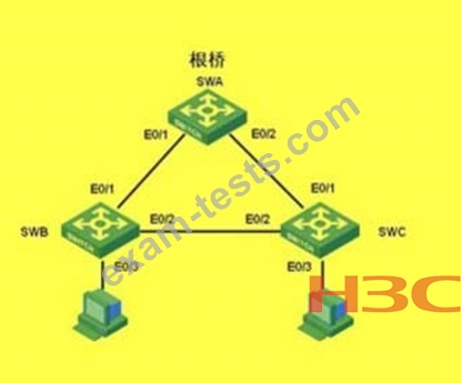
Question 14
As shown in the networking, the switch enables RSTP, and the following statements about its configuration are correct.
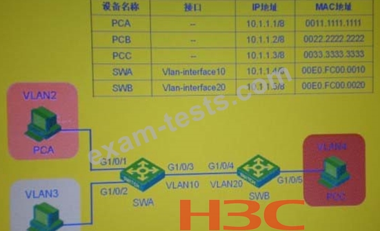
Question 15
In the switching network as shown in the figure, VLAN10 is set as Isolate-user-vlan on switch SWA, VLAN2 and VLAN3 are set as Secondary VLAN of VLAN 10; VLAN2-VLAN20 is created on switch SWB, and VLAN20 is set as Isolate-user-vlan , VLAN4 is the Secondary VLAN of VLAN20. After setting the IP address of each device as shown in the figure, the local proxy ARP function is enabled on both SWA and SWB. Initially, the switch and pc did not learn their corresponding ARP entries. In the process of PCA ping PCB, PCA will send an ARP request. After receiving the ARP request message, the PCA will send the destination MAC response. The destination MAC address is