
Question 56
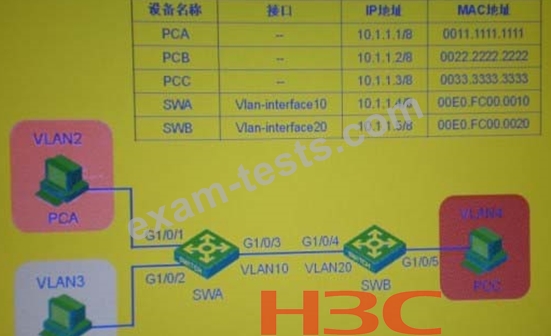
In the switching network as shown in the figure, set VLAN10 as Isolate-userW VLAN2 and VLAN3 as the Secondary VLAN of VLAN 10 on the switch SWA; create VLAN2? VLAN20 on the switch SWB, and set VLAN20 as Isolate-user-vlan, VLAN4 For the Secondary VLAN of VLAN20, after setting the IP address of each device as shown in the figure, which statement is correct (choose one or more)
Question 57
In the networking model shown in the figure, if Accoing is received on RADIUsClient, the following statement may be correct.
Question 58
Regarding the configuration BPDU and TCM BPDU, the statements are correct
Question 59
In the switching network as shown in the figure, set VLAN10 as Isolate-userW, VLAN2 and VLAN3 as the Secondary VLAN of VLAN 10 on the switch SWA; create VLAN2? VLAN20 on the switch SWB, and set VLAN20 as Isolate-user-vlan, VLAN4 As the Secondary VLAN of VLAN20, after setting the IP address of each device as shown in the figure, check the MAC address table on the SWA, and you can determine that the PCC belongs to
Question 60
The following statements about BSR and RP in PIMSM are correct: