Question 61
In the network as shown in the figure, the corresponding configuration is completed on the switch SWA, and the switch SWA and each PC have learned the corresponding ARP entry. The PCA visited the PCB and sent an ICMP request message, and the switch SWA forwarded this message to the PCB. When the source IP address of the packet is
Question 62
The two routers are connected through a LAN to form a VRRP backup group, and the configuration on each interface is as follows:
[RTA-GigabitEthernet1/0]display this
ip address 192.168.0.252 255.255.255.0
vrrp vrid 1 virtual-ip 192.168.0.254
[RTB-GigabitEthernet1/0]display this
ip address 192.168.0.253 255.255.255.0
vrrp vrid 1 virtual-ip 192.168.0.254
It can be known from the above information
[RTA-GigabitEthernet1/0]display this
ip address 192.168.0.252 255.255.255.0
vrrp vrid 1 virtual-ip 192.168.0.254
[RTB-GigabitEthernet1/0]display this
ip address 192.168.0.253 255.255.255.0
vrrp vrid 1 virtual-ip 192.168.0.254
It can be known from the above information
Question 63
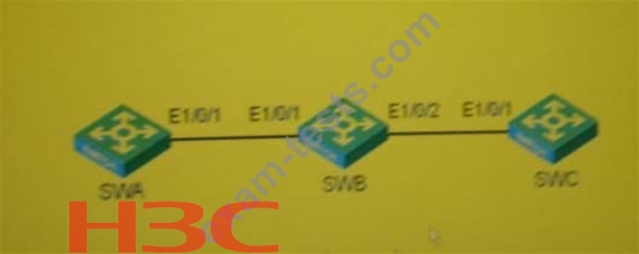
In the switching network as shown in the figure, all three switches only have the default VLAN 1, the interconnection ports of the three switches are Trunk, and all VLANs are allowed to pass, and the three switches have the global and port GVRP function enabled. VLAN 10 is created on the switch SVVA, VLAN 20 is created on the switch SWC, check the status information of each Trunk port on the three switches, the correct one is displayed below (choose one or more)
Question 64
Regarding the port status and role in RSTP, what are the correct statements?
Question 65
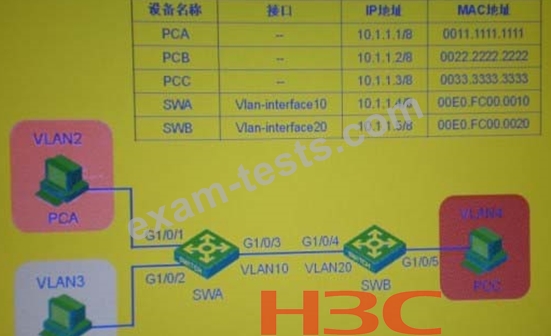
In the switching network as shown in the figure, VLAN10 is set as Isolate-user-vlan on switch SWA, VLAN2 and VLAN3 are set as Secondary VLAN of VLAN 10; VLAN2? VLAN20 is created on switch SWB, and VLAN20 is set as Isolate-user-vlan , VLAN4 is VLAN20 Secondary VLA after setting the IP address of each device as shown in the figure, if the local proxy ARP function is enabled on both SWA and SWB, and both SWA and SWB are allowed to send ICMP packets, then on PCA Execute the command tracert 10.1.1.2, the PCA will show that it needs to go through a jump to reach the PCB (please fill in the Arabic numbers)